Heat Pump Refrigerant Flow Diagram Heat Mode Refrigeration:
4.4 the first law of thermodynamics for closed systems – introduction Heat pump refrigerant flow diagram 2: heat pump operating fundamentals
Pin by BLCKTCH on Mechanical Engineering
Heat pump cycle diagram pumps condenser compressor explained expansion valve figure shown Heat pump refrigerant flow diagram Heat pump refrigerant flow diagram
Heat pump cycle fundamentals
6.2 refrigerator and heat pump – introduction to engineering thermodynamicsReversing heating condenser evaporator refrigerant hvac vice versa hvacrschool Heat pump refrigerant flow diagramHeat pump refrigerant circuit diagram.
How a heat pump worksSolved: figure p6.90 shows a schematic diagram of a heat pump using Refrigerant refrigeration hvac hvacrschool wiring cooling pump checking gauges cucv linesHeat pump refrigerant circuit diagram.

Heat pump refrigerant flow diagram
Heat pump refrigerant flow chartHeat pump refrigerant circuit diagram Hvac/r refrigerant cycle basicsPump representation refrigerant schematic gshp interchange water.
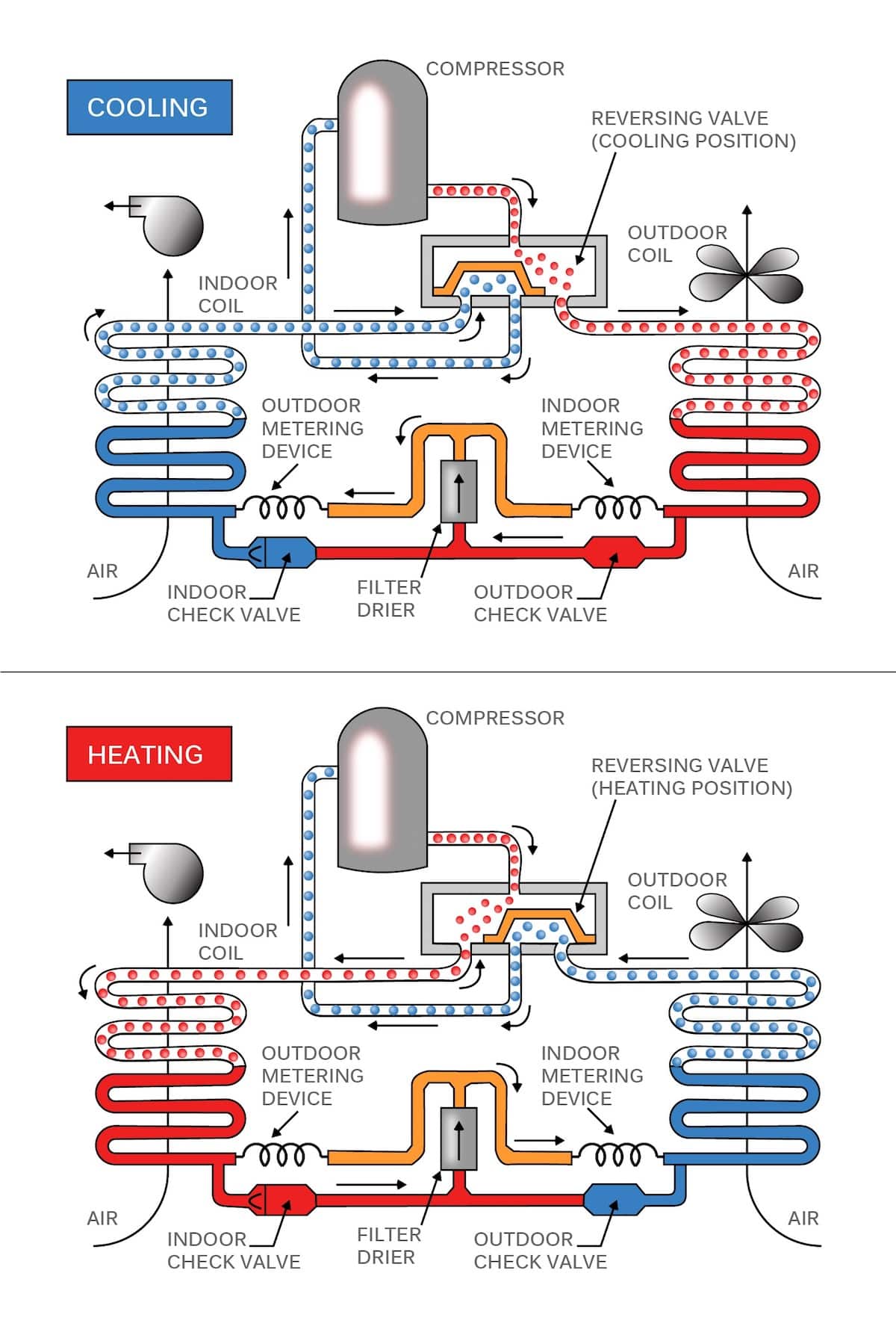
Pump heat valve reversing air conditioning hvac cooling refrigeration conditioner mode system cycle way compressor flow freon diagram refrigerant circuitHow to check refrigerant level in heat pump? Heat pump work works long does installation island pumps replacement systems energy types repair should get service choose board geothermalSolved a heat pump uses r134a as a refrigerant. the.

Pin by blcktch on mechanical engineering
With up to 65% more efficiency, how do heat pumps work?Heat pump operating figure fundamentals caleffi component Understanding hvac: how heating and cooling systems workRefrigerant circuit basics (podcast short #1).
How a heat pump reversing valve worksRefrigeration refrigerant function inverter calgary Heat pumps explainedHeat pump inverter systems.

2hp common refrigerant expansion valves economizer provide complete
Minisplit: 4. testing and refrigerant – papa moHeat pump cycle: schematic representation in heating mode. the Heat pump reversing valve heat pump air conditioner, air conditionerHeat pump refrigerant flow diagram.
Heat air pump source heating pumps conditioning thermostat cycle refrigeration problems house water mode gif refrigerant refrigerator compressor installed linedHeat pump refrigerant flow diagram Refrigeration: heat pump refrigeration schematic[diagram] florida heat pump piping diagram.


![[DIAGRAM] Florida Heat Pump Piping Diagram - MYDIAGRAM.ONLINE](https://i2.wp.com/www.refrigerationbasics.com/RBIII/hp_blank.png)


